


Technological Realisations
The Savona Combustion Laboratory (DIMSET/SCL) is located north of the campus of the Savona School of Engineering, taking its extension within two separate buildings: the right "wing" of the Lab (devoted to liquid-fuel combustion systems, and thus named "LF Area") occupies a 13 x 10 m2 masonry building, whilst on the left the Lab takes its place within a 30.5 x 15.5 m2 hangar, mainly dedicated to natural gas-fueled combustion systems testing ("NGF Area"). Both buildings, formerly of military property, will progressively undergo a series of structural and aesthetic restorations, while keeping operativity (plant view of LF building, with the layout of the LRPM burner test-rig, as well as the location of the Deutz diesel engine utilised for electric power self-generation, up to 150 kW). As of now, the electrical air-preheating equipment of the burner test-rig, absorbing about 110 kW so to reach 500°C at full flow-rate, is fed by this latter power source. In a near future, a 200 kW electric-power line will be available. Closely outside of the LF building, a 2.0 m3 liquid-fuel store-tank is located, feeding, under totally independent circuits, both the burner test-rig and the diesel engine.
In the NGF hangar, a natural-gas burner-testing furnace of 1000 kW thermal-power is located, whilst a project is under development for installing a mid-pressure (4 bar) gas-turbine burner test-rig, fueled with natural gas and possibly other gaseous fuels (syngas, hydrogen).
As above said, in order to experimentally test liquid fueled gas-turbine burners of various typologies, and, more specifically, premixer-burners of LRPM technology, a dedicated, variable-geometry, atmospheric-pressure test-rig (an isometric view of the overall test-rig), with an air pre-heating electrical capability of up to about 500 °C, has been designed, manufactured and erected in the LF building (an isometric rendering of the Laboratory with the remotely pc-controlled burner-rig installed in the heat-shielded, fire-proof area of the Lab) of DIMSET/SCL. In the same isometric view of the test-rig , the 3 electrical preheaters (35 kW each) installed upstream of the plenum chamber and the 9 traversing-stations locations provided along the combustor length for reactive-flow sampling are visible, as well as the water-jacketed vertical discharge duct, leading the exhaust gasses up to the outside stack, above the building roof.
Since the LRPM strategy is basically rooted on physical principles, mainly of fluid-dynamical (more than thermo-chemical) nature, it is expected that, once satisfied the geometry, temperature, Reynolds and Mach number similarities, together with a reasonably sound interpretation of the parameters governing spray-droplets behavior, the constraint of atmospheric pressure for the test-rig will not sensibly affect the validity of the experimental outcome and its transposition to the actual operating pressure.
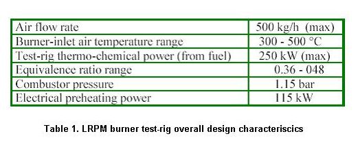
The radial-inflow LRPM burner prototype (CAD sectional drawings of the inward-radial-swirl LRPM burner geometry) has been manufactured and installed, together with its inner-duct axial-extension (30 mm length, 87 mm i.d., of crucial importance for premixing process and flame stability), in between the 400 mm i.d. plenum chamber (for flow and temperature uniformisation) and the 150 mm i.d. combustor (25/35 Ni/Cr alloy, outer side unshielded, inner side thermally coated). The design and operational characteristics of the test rig are synthetically shown in Table 1 .
As above said, the test-rig equipped with the LRPM premixer-burner is now ready to undergo the first pre-operational tests. Its instrumentation, in addition to the classical optical pyrometry, direct-sampling water-cooled traversing-probes (9 traversing stations along the combustor length) and several wall-temperature monitoring-points (thermocouples) already operational, will soon entail advanced laser-based diagnostics. To this latter end, and always within the frame of the MURST Program (Cluster 21) sponsoring this research endeavor, a close cooperation is already planned between DIMSET/SCL and ENEA, the Italian National Center for Energy, in order to jointly proceed with the application of advanced combustion-diagnostics instrumentation to the experimental campaigns to be performed on the test-rig here discussed.
Scientific Bases of LRPM Strategy
The proposed solution to this problem resorts to the intrinsic capacity of the turbulence kinetic energy, for the larger scales, and, more specifically for the smaller scales, of its dissipation rate, to rapidly disaggregate the flow eddies into ever smaller structures and then to "molecularly diffuse" their residual dynamics into heat. If the burner design could impose that, from a physical/fluid-dynamical point of view, the turbulent kinetic energy and its dissipation rate would be maintained, in localised regions, at their maxima, then these regions (typically represented by high-shear layers) could be selected as the most suitable for "localised" injections of the liquid fuel, thus providing a strong "drive" to its vaporisation and turbulent mixing.
In addition, if, in these regions, any recirculation of the flow could be avoided by design, so to limit at a minimum the residence times, then the overall process could, expectedly, enter the "ultra low emissions" regime. Finally, if the fuel-injection modality could maintain a well-defined, directional, fuel-concentration gradient in the air shear layer immediately ahead of the flame front, then the combustion process will be free of thermo-acoustical instabilities, typically related to non-directional premixing modalities.
Theoretical Analysis and Design Development
In order to refine and support theoretically the LRPM burner design, with specific reference to the crucial two-phase liquid-fuel premixing process in presence of the counter-flow influences (mass and heat convection, heat radiation, possible thermo-acoustic perturbations, etc.) coming from the flame process, a fully 3D time-dependent turbulent reactive Navier-Stokes analysis has been performed by applying, with parametric modalities, NastComb, the CRFD ("computational reactive fluid dynamics") Navier-Stokes solver developed at DIMSET during the last 12 years (Pittaluga, 1993; Pittaluga et al., 1994; Pittaluga et al., June 1998; Pittaluga et al., Aug. 1998; Duranti & Pittaluga, 1997; Duranti & Pittaluga, May 1999; Duranti & Pittaluga, 2000; Luccoli et al., 1996; Luccoli et al., 1997; Traverso, 2000). Since, under many respects, the design activities, the technological developments, and even the experimental testing, all pursued within the Savona Combustion Laboratory, are closely interlinked with parallel and complementary numerical analyses performed by means of the said solver, a synthetic presentation of its features, some of which are at all unique, is here deemed important.
NastComb is the combustive extension of Nast, a finite-volume, 3D, fully time-dependent, turbulent, compressible thermo-fluid-dynamical Navier-Stokes solver of ALE (arbitrary lagrangian-eulerian) solution strategy, in which every time-step consists of a lagrangian phase, with the flow velocities applied to the (moving) grid vertexes ( multi-block mesh-sector utilised for the computations), followed by a convective phase, i.e. a rezoning of the (updated) flow field, performed by displacing the grid back to its initial position. A monotone, nearly second-order (QSOU), differencing scheme is applied for convection, with use of cell-face velocities in order to lower numerical diffusion. To increase numerical efficiency, a pressure-gradient scaling (PGS) algorithm is activated whenever flow velocities are particularly low. Grid types are staggered, boundary fitted, multi-block, with hexahedroidal cells (Duranti & Pittaluga, 1997).
The governing equations for 3D, fully time-dependent, turbulent, variable-density, reactive flow, in presence of conduction and radiation, formerly of favre-average formulation, have recently been converted into ensemble-average form (Duranti & Pittaluga, 2000), in order to take full advantage of the Markovian revisitation performed on its turbulence model. This latter, developed and validated along several years, is a three-equation, non-linear eddy-viscosity approach based on the so-called "two-scale direct-interaction approximation" (TSDIA) with a Markovian simplification (MTS) for the solution of the approximate equations for fluctuations (Duranti & Pittaluga, May 1999). The model accounts for variable-density effects via a transport equation for the density-variance, which corrects the eddy-viscosity, and is thus particularly suited to track the interactions between turbulence and the density variations as induced by the reactive field.
Combustion simulation is performed following a "partial-equilibrium" approach, whereby all reactions are pre-partitioned in two groups, the "slow" ones, which proceed kinetically (Arrhenius kinetics assumed), and the "fast" reactions, assumed in equilibrium at all times. Both global schemes (Duranti et al., May 2000) and quasi-global, partial-oxidation, schemes (Pittaluga, 1994; Luccoli et al., 1997) have been developed. On the other side, in order to more correctly "detail" these schemes, a limited set (12 to 16) of elementary reactions is anyhow adjoint and programmed. In addition to fuel (gas or liquid), the species considered are, typically, the following: O2, O, CO, CO2, H2, H2O, H, OH, N2, N, NO. A detailed chemistry, parallel/clusterised version of NastComb is under development, taking advantage of financial sponsorships from MURST (co-financed national-interest program) as well as the European Commission (ICLEAC Program).
In order to take care of turbulence effects, the expression of the total combustion time t c is evaluated in Nastcomb as the sum of a molecular time-scale t 1 (the inverse of either the global or the quasi-global reaction rate, according to the scheme adopted) and a turbulent time-scale tt (related to the eddy turnover time):
= + f


where the delay coefficient f , aimed at further correcting (i.e. "delaying") the implications of reaction completeness induced by the global assumption (if adopted), has been assigned the expression :
f = ( 1 e r )/ 0.632
where r is the local ratio of the mass of products to that of total reactive species (Duranti et al., May 2000). Of course, to f a unit value is assigned when no assumption of reaction completeness is implied, i.e. when the overall reaction is of quasi-global type (partial-oxidation).
For liquid fuels, the treatment of fuel spray dynamics in NastComb is based on a Monte Carlo method and adopts the concept of "discrete particles". Strategy is that of sampling randomly from assumed probability distributions that govern droplet properties at injection and droplet behavior subsequent to injection. Turbulent correlation times associated with proper distributions of turbulent displacements for spray droplets are considered. The stochastic particle method is suitable to calculate evaporating liquid sprays including the effect of droplet collisions, coalescence and aerodynamic breakups (secondary atomisation) (Duranti et al., May 2000).
In Nastcomb solver a detailed, non-equilibrium, continuous-field, time-dependent 3D radiation model has been introduced, and made interactive with the overall turbulent reactive thermo-fluid-dynamical solution. Originally the model, of a "neutronic" character, was developed within a 2D, equilibrium assumption for the radiation diffusion treatment. Then, the scheme has been extended to nonequilibrium diffusion, wherein the gas and the radiation fields can have different temperatures, and flux-limiters are adopted to extend the diffusion theory to optically-thin regions, with also 3D capability (Pittaluga et al., 1998; Duranti et al., 2000). In synthesis, the transport equation for the radiation energy-density is solved fully coupled with the gas energy-density equation. The coupling terms which relate the radiation energy density to the fluid energy density are large when the photon mean-free paths due to molecular collisions are small ("optically-thick" regions) whilst the opposite is true in "optically thin" regions.
At the end of the computations can be obtained predictions of the turbulent kinetic energy, its dissipation rate, pressure and temperature distributions in a meridian plane of the combustor. The solution is fully 3D and reactive. Notice that the picture changes for different meridian planes, in particular for the k and e distributions, which gives extremely important information about the correct azymuthal orientation of fuel injection holes, in order, for the spray droplets, to attain exactly into the dissipation rate peaks.
Finally it also can be seen a perspective internal view is given of the burner-combustor assembly with the eight-vane radial-inflow premixer: the flow is from bottom to top. The liquid fuel (typically: "jet-A" for aero-propulsion applications, or "distillate #2" for heavy-duty gas turbines) is injected either radially inward, within each one of the 8 vane-channels or, alternatively, directly from the premixer "eye", on the burner centerline. In this latter case, the fuel is introduced by means of an eight-faceted conical injector, provided with one 0.4 mm injecton hole for each (locally planar) facet, with an injection-path azymuthal setting and meridian-plane orientation suitable to attain exactly into the shear layers produced by the radial vanes.


Research Projects


In order to attain the highly difficult target, for a liquid-fueled gas-turbine combustor, of containing pollutant emissions within one-digit-ppm limit, a peculiar strategy has been followed and transferred into burner-design technological-landmarks. The conceptual cornerstones which the strategy is based on do not belong mainly to the chemistry realm, rather they involve clear physical principles of basic fluid-dynamical nature, in close connection with two-phase flows and turbulence theory.
The sequential reasoning which motivates the LRPM strategy (for "Liquid-fuel Rapid Pre-Mix") can be here synthesised as follows. In order to achieve a strong containment of NOx emissions, flame temperatures must be kept as low as possible, compatible with flammability limits, whilst oxygen concentration must be provided at high levels and at a well-mixed condition (molecularly with fuel) in order to prevent CO production. Whilst the flame temperature constraint can be tackled by adoption of ultra-lean equivalence ratios, the core problem, particularly with liquid fuels, is the attainment of mixtures molecular premixing, which, by its side, pre-requires a rapid and complete vaporisation of the liquid droplets.
The sequential reasoning which motivates the LRPM strategy (for "Liquid-fuel Rapid Pre-Mix") can be here synthesised as follows. In order to achieve a strong containment of NOx emissions, flame temperatures must be kept as low as possible, compatible with flammability limits, whilst oxygen concentration must be provided at high levels and at a well-mixed condition (molecularly with fuel) in order to prevent CO production. Whilst the flame temperature constraint can be tackled by adoption of ultra-lean equivalence ratios, the core problem, particularly with liquid fuels, is the attainment of mixtures molecular premixing, which, by its side, pre-requires a rapid and complete vaporisation of the liquid droplets.
In order to experimentally test liquid fueled gas-turbine burners of various typologies, and, more specifically, premixer-burners of LRPM technology, a dedicated, variable-geometry, atmospheric-pressure test-rig, with air pre-heating electrical capability of up to about 500 °C, has been designed, erected and made fully operative in a dedicated wing of SCL Laboratory. Since LRPM strategy is basically rooted on physical principles, mainly of fluid-dynamical (more than thermo-chemical) nature, it is expected that, once satisfied dimensional, temperature, Reynolds and Mach number similarities, together with a reasonably sound interpretation of the parameters governing spray-droplets behavior, the constraint of atmospheric pressure for the test-rig will not sensibly affect the validity of the experimental outcome and its transposition to the real-duty pressure. In order to experimentally test liquid fueled gas-turbine burners of various typologies, and, more specifically, premixer-burners of LRPM technology, a dedicated, variable-geometry, atmospheric-pressure test-rig, with air pre-heating electrical capability of up to about 500 °C, has been designed, erected and made fully operative in a dedicated wing of SCL Laboratory. Since LRPM strategy is basically rooted on physical principles, mainly of fluid-dynamical (more than thermo-chemical) nature, it is expected that, once satisfied dimensional, temperature, Reynolds and Mach number similarities, together with a reasonably sound interpretation of the parameters governing spray-droplets behavior, the constraint of atmospheric pressure for the test-rig will not sensibly affect the validity of the experimental outcome and its transposition to the real-duty pressure. A picture of the LRPM burner test-rig is given in Figure 1. In the same Figure, the 3 electrical preheaters (35 kW each) installed upstream of the plenum chamber are visible, as well as the water-jacketed vertical discharge duct, leading the exhaust gasses up to the outside stack, above the building roof.
Outcome of Performance Testing
The main characteristics of the test-rig are reported in Table 1. Starting from about one year ago, a series of experimental campaigns have been performed in order to directly assess the validity of the LRPM concept, above discussed from a theoretical point of view. Thanks to the cooperation with ENEA, the Italian National Center for Clean Energy, it has become possible to jointly proceed with the application of advanced combustion instrumentation, with the aim of achieving a series of reliable and detailed diagnostic pictures, particularly in connection with the flame process characterisation, the emissions assessment and the combustion stability analysis.
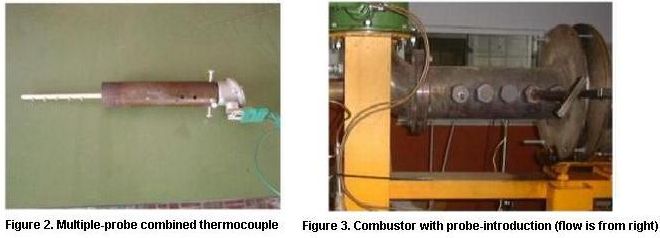
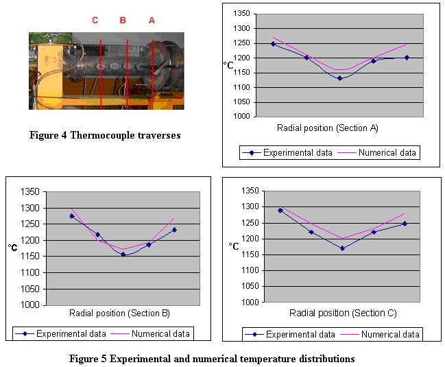
In order to assess the flame process characteristics within the combustor, it is crucial to achieve a map of the temperatures within the combustion chamber. To this end, in addition to the 8 "skin-point" thermocouples provided on the walls of the combustor, along its axial length, a special 5- probe combined-thermocouple has been utilised, expressly designed and manufactured for this application. In order to sustain flame temperatures up to 1700 °C, it is made completely in ceramics (no metal parts inside), with fully embedded probe-wiring, which thus turns out highly shielded from the outside. It is pictured in Figure 2, whereas Figure 3 shows its introduction holes provided into the combustor walls. Notice that as many holes, with displaced locations, are also provided on the diametrically opposite wall.
Figure 5 presents the experimental temperature distribution, compared with NastComb's predictions: the comparison turns out satisfactory, some times rather good. Notice the absence of peak temperatures above 1350 °C and a very smooth temperature distribution in the whole chamber, confirming attainment of adequate premixing levels ahead of the flame front.
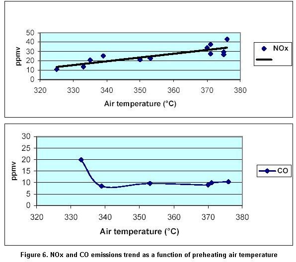
On the other hand, a careful analysis of the exhaust gasses is mandatory in order to check the achievement of the ultra-low emission regime, in terms of NOx and CO. To this end, the combustion gasses are sampled about 1.5 m duct-length downstream of the combustor, after the exhaust cooling section, in a location where the recombination processes should be largely attained. The exhaust gasses of the combustor are analysed by means of two different diagnostic instruments, namely, a Chemical Ionization Mass Spectrometer (Airsense 500) and a Fourier Transform Infrared Spectroscope (FTIR). The first instrument is based on an ionization system with charge exchange. It yields the qualitative and quantitative determination of the molecular components of the exhaust gasses, operating in real time (Tmin = 1 ms) and with a very high resolution (0.001 ppm). The FTIR instrument is based on the characteristic absorption of the infrared radiation by the different chemical species, allowing to measure up to 12 different species simultaneously. It is characterised by high stability and easy calibration, thus assuring a very simple and quick utilisation. The CO and NOx emission trend measured as a function of the preheating temperature of the air is presented in Figure 6. Notice the full attainment of the ultra-low regime, a very important result, particularly in connection with a liquid fuel such as gas-oil. Notice also that the NOx emission levels are throughout very low and that, quite importantly, they decrease by lowering the preheated air temperature, thus limiting the thermal NOx production. This shows that the attainment of a good premixed condition has been satisfied for the whole range of preheating temperatures, with the additional evidence that the said condition is achieved not by thermo-dynamical means (i.e. increase of temperature, enhancing droplet vaporisation), rather, thanks to fluid-dynamical reasons (i.e. turbulence-controlled process).
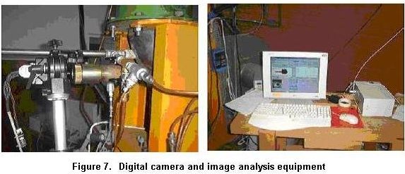
Notice how clearly, from a perspective of emissions' control, the optimised operational characteristics of the burner can be definitely assessed from Figure 6. Actually, thermal NOx is steadily decreasing with the decrease of the air preheating temperatures. On the other hand, CO emissions are almost constant until the air temperature gets lower than about 340 °C. Thus, the latter condition turns out as the most suitable to limit to an extremely low level the environmental impact of the combustion system. Notice also that the emissions levels shown throughout Figure 6, and not just at the optimal point, are amply contained within the ultra-low emissions range for gasoil. Finally, in order to experimentally investigate the stability characteristics of the LRPM burner, in particular connection with its thermo-acoustical stability, in addition to the adoption of classical pressure transducers, an innovative detection technique has been developed and successfully applied, now subject to become patented. The technique is based on digital optics and employs a digital camera (Dalsa CA-D1, 128x128, 736 frames/s) that, at a high speed, takes and collects images of the flame process (Figure 7).
The images are, in real time, elaborated by a specialised software that evaluates the flame brightness gradient (first-order time-derivative). By performing a fourier transform on these data, the characteristic frequency of the light fluctuation is obtained. Interestingly, this frequency turns out exactly the same as that of the pressure oscillations. It is thus correct to analyse the combustion instability by adopting this digital/optical technique which appears suitable not just to detect the actual presence of instability pulsations, as is the case of the pressure transducers, but also of predicting their occurrence with an advance-time of the order of one second, to the advantage of a control action preventing the instability to occur.